
Two measuring principles
Thermocouple or PT100?
Thermocouples and PT100 sensors both measure temperature, but they operate in fundamentally different ways. A thermocouple generates a very small voltage, while a PT100 changes its electrical resistance as its temperature changes.
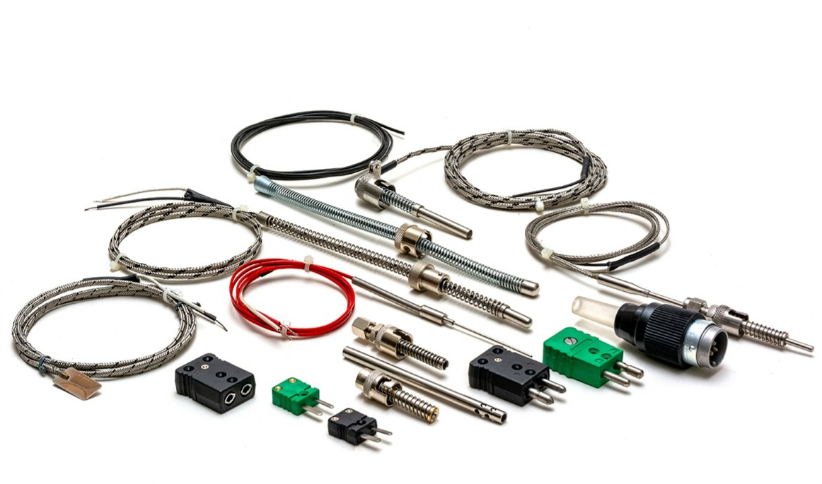 Hotset thermocouples in a variety of sheath, cable, connector and termination arrangements
Two different metal alloys form a measuring junction. The temperature difference between this junction and the instrument connection produces a small voltage.
A platinum sensing element has a nominal resistance of 100 ohms at 0°C. Its resistance increases in a predictable way as its temperature rises.
Common thermocouple types
Type J, Type K or Type T?
Each thermocouple type uses a different pair of metal alloys. This affects its useful temperature capability, environmental suitability, stability and cost.
Iron / Constantan
Advantages
- Good sensitivity through a useful industrial temperature range
- Common and economical for plastics machinery and general equipment
- Often suitable in vacuum, inert and reducing atmospheres within the assembly’s rating
Limitations
- The iron leg oxidises and can rust, particularly where moisture is present
- Lower upper-temperature capability than Type K
- Generally unsuitable for prolonged high-temperature use in oxidising atmospheres
- Operating Range 0°C to 750°C
Nickel-Chromium / Nickel-Aluminium
Advantages
- Broad practical temperature capability
- Good general-purpose choice in oxidising or inert atmospheres
- Widely available in many probe, cable and connector constructions
Limitations
- Can drift after prolonged high-temperature exposure
- Not automatically suitable for reducing, sulphurous or low-oxygen high-temperature atmospheres
- Usually costs more than an equivalent basic Type J assembly
- Operating Range 0°C to 1100°C
Copper / Constantan
Advantages
- Good stability and repeatability at lower temperatures
- Well suited to low-temperature and sub-zero measurement
- Useful in food, refrigeration and laboratory applications
Limitations
- Lower upper-temperature capability than Types J and K
- The copper conductor oxidises at elevated temperatures
- Usually selected for lower-temperature duties
- Operating Range −200°C to 300°C
Iron
Nickel-Chromium
Copper
Copper-Nickel (Constantan)
Nickel-Aluminium
Copper-Nickel (Constantan)
Economical general industrial measurement
Wider temperature range and broad availability
Stable lower-temperature measurement
Oxidation and corrosion of the iron leg
Atmosphere-related drift and instability at elevated temperature
Limited elevated-temperature capability
Black overall; black positive, white negative
Green overall; green positive, white negative
Brown overall; brown positive, white negative
Platinum resistance sensors
Understanding PT100 sensors
A PT100 is a resistance temperature detector, commonly called an RTD. Its platinum sensing element has a nominal resistance of 100 ohms at 0°C and follows a defined resistance-to-temperature relationship.
The measuring instrument passes a small current through the platinum element, measures its resistance and converts that resistance into temperature.
Good accuracy
PT100 sensors are frequently selected where measurement accuracy is more important than the widest possible temperature range.
Good stability
Platinum provides a stable and repeatable resistance-to-temperature relationship.
Near-linear response
The resistance changes predictably with temperature, making PT100 sensors suitable for industrial measurement and control.
Different instrument input
A PT100 must be connected to an RTD-compatible controller, transmitter or indicator—not a thermocouple input.
Two-, three- or four-wire connection?
Simple connection
The resistance of both connecting leads is added to the sensing-element resistance and therefore introduces a measurement error.
ConsiderBest suited where cable runs are short and the required accuracy permits the additional lead-resistance error.
Lead compensation
The measuring instrument compensates for most lead resistance, provided the lead conductors have closely matched resistance.
ConsiderA widely used industrial compromise between accuracy, cable complexity and cost.
Highest accuracy
Separate current and measurement conductors allow the instrument to remove lead resistance from the measurement.
ConsiderPreferred where the greatest measurement accuracy is required.
At the sensing tip
Grounded, isolated or exposed?
The junction arrangement changes response speed, electrical isolation and environmental protection. “Isolated” is also commonly described as an ungrounded junction.
Fast sheathed response
The measuring junction is welded to the metal sheath. Heat passes directly from the sheath to the junction, giving a relatively fast response.
AdvantageFast response with the mechanical protection of a sheath.
ConsiderThe thermocouple circuit is electrically connected to the sheath, which can introduce ground-loop or electrical-noise problems in some installations.
Electrical separation
The junction is insulated from the sheath, normally within compacted mineral insulation.
AdvantageBetter electrical isolation from the machine or process and often the safest choice where noise or multiple earth paths are a concern.
ConsiderResponse is normally slower than an otherwise equivalent grounded junction.
Fastest direct response
The measuring junction projects beyond the protective sheath and is directly exposed to the medium.
AdvantageVery low thermal mass and rapid response.
ConsiderLeast protected from impact, pressure, corrosion and contamination; unsuitable for many industrial environments.
The rest of the sensor matters
Construction choices that change performance
Sheath diameter
A smaller diameter usually responds faster; a larger sheath is generally more mechanically robust.
Sheath material
Stainless steels and nickel alloys offer different temperature and corrosion capabilities. Select for the actual atmosphere or process medium.
Insertion depth
Too little immersion allows heat to conduct away along the sheath and can produce a reading that does not represent the process.
Tip contact
A surface sensor, spring-loaded bayonet and immersed probe each need different geometry to put the junction where temperature is to be measured.
Cable insulation
Fibreglass, PTFE, silicone and other constructions have different temperature, flexing, moisture and abrasion capabilities.
Termination
Plugs, sockets, heads, tails, threads and bayonet fittings must match the installation and remain within their own temperature ratings.
Avoid false readings
Wiring, polarity and interference
Polarity must remain correct
Reversing the positive and negative conductors can drive the indicated temperature in the wrong direction or create a plausible but incorrect reading.
Use matching extension cable
Do not extend a thermocouple with ordinary copper cable unless the measuring system is specifically designed for that transition. Use the correct thermocouple or compensating cable for the type and temperature involved.
Check the thermocouple colour standard
Under IEC thermocouple colour coding, the negative conductor is white. Type J is identified by black, Type K by green and Type T by brown. ANSI and other standards use different colours, so never identify an unknown sensor by colour alone.
Route away from power
The signal is measured in millivolts. Keep sensor cable away from heater power, motors, contactors and variable-frequency drive wiring; use suitable screened cable and grounding practice where required.
Preparing an enquiry
What Hotset needs to know
Send us the application, drawing or sample.
Hotset can manufacture thermocouples and PT100 sensors around the temperature, environment, accuracy and mechanical installation.