
Before the dimensions
Start with the application
A replacement heater can often be identified from its markings or an existing drawing. For a new application, tell us what needs heating and how the heater will be installed.
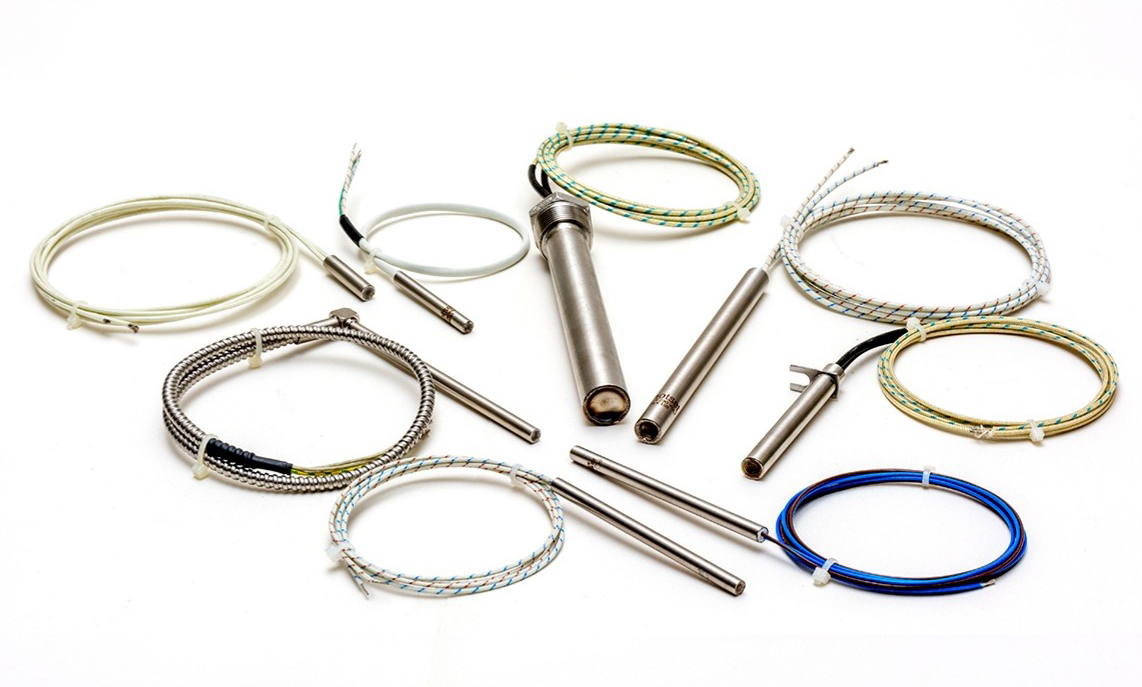 Examples of Hotset cartridge-heater constructions and lead arrangements
Useful starting information includes the material being heated, required operating temperature, desired heat-up time, available supply voltage, control method and any exposure to moisture, oil, vibration, vacuum or movement.
Step 01
Diameter, length and fit
Diameter
State the required heater diameter and the measured bore diameter. At higher watt densities, a close, correctly toleranced fit becomes particularly important for transferring heat into the surrounding metal.
Overall length
Measure the metal sheath only and identify whether any fitting, flange or termination must be included separately. If known, also state the required heated and cold lengths.
Bore and installation
Tell us whether the hole is drilled, reamed, blind or through, together with the material of the part. A through-hole can make eventual heater removal considerably easier.
Quantity and position
For a platen or tool using several heaters, include their spacing and sensor location. Even heat distribution may matter more than concentrating all power into fewer heaters.
Step 02
Voltage, wattage and temperature
Voltage
State the actual supply voltage applied across each heater—not merely the machine’s incoming supply.
Wattage
State the required power per heater. For a new design, include the mass, material, temperatures and heat-up time so the requirement can be reviewed.
Temperature
Give both the normal process temperature and any maximum or exceptional operating condition.
These figures determine the heater’s electrical design and surface watt density. A high wattage in a small sheath can be appropriate when fit and heat transfer are excellent, but the same rating may give poor life in an oversized bore or a low-conductivity material.
Step 03
Choose the termination
The lead end is often where the application places the greatest mechanical and environmental demands on a cartridge heater. Tell us how the cable needs to leave the sheath and what it must withstand.
Straight leads
Lead wires leave axially from the end of the heater.
Right-angle leads
Useful where axial space is restricted or wiring must run beside the tool.
Metal braid or conduit
Added protection against abrasion and handling damage.
Terminal pins or posts
A rigid connection option for suitable installations and electrical arrangements.
Step 04
Useful options to identify
Built-in sensor
State thermocouple type, junction position and whether it is grounded or isolated, if required.
Distributed wattage
Different power loading along the heated length can compensate for unequal process losses.
Cold sections
Identify areas that must remain unheated, especially near seals, leads or temperature-sensitive components.
Fittings and flanges
Provide thread, material, position and dimensional details for mounting hardware.
Sealing
Tell us about moisture, cleaning fluids, oil, vacuum or other conditions affecting the lead-end seal.
Special geometry
Drawings are recommended for unusual tips, internal sensors, stepped diameters or other special features.
Prepare an enquiry
Build your specification
Complete what you know. Unknown details can be left blank and discussed with our technical team.
Send the specification, drawing or sample.
We’ll review the practical details before providing a quotation.